The following is a partial list of useful features to give the user an indication of the versatility of SimuPec:
- Two power electronics simulators; SimuPec® which is a conventional non fixed admittance simulator and SimuPec_FA® the Fixed admittance matrix simulator.
- Circuit Partitioning and decoupling (for both Simulators SimuPec_FA and SimuPec)
- Interactive and Dynamic Parameters Variation (non-fixed admittance Simulator SimuPec only)
- Modeling of Nonlinear and Time Variant Components
- Modular multilevel converter blockset “MMC-BLOCKSET”
SimuPec® and SimuPec_FA®:
SimuPec® is a conventional non fixed admittance simulator and SimuPec_FA® the Fixed admittance matrix simulator. Both of them can simulate the same power elecronics system without any modifications of the C-Circuit describtion file.
Circuit Partitioning and decoupling:
SimuPec® and SimuPecFA® make use of system-partitioning by dividing the whole large scaled power electronics system containing thousands of switching device, thermal and electromechanical devices into many small sub-systems with different scale of time constants. This leads to remarkable speedup over single system (single very large system matrix).
A single time step delay is needed only if the S-function block needs to communicate with other blocks, for example in the MMC-converter there is no need of any time delay between the S-function blocks of the converter arms because there are no communications needed between each others. Between the S-function block of the converter arms and the main power supply circuit you should add single time step delay.
The figure below shows one MMC-converter station modeled as 7 Simulink blocks. One Simulink block for each arm (half leg) of the converter and one Simulink block for the power supply circuit.
The circuit topoloy of the 6-arms of converter are exsactly the same, they make use the same paramter-vector, however they need different input-vector and deliver different output-vector. Therefor you need to model only one converter arm and use it (copy and paste) for the other converter arms after modification of the respective input-vector and output-vector.
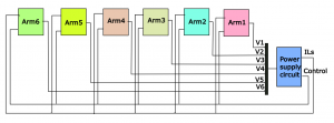
MMC Conveter station modeled as 7 S-function blocks
The basic model of the switching devices by the fixed admittance Simulator is a fixed admittance G=1/ohm during both switching states; although different values are used in the history source current Vector.
By the non fixed admittance Simulator, the basic model of the switching device is a piecewise linear model. The resistance value changes according to the switching state, it takes a very high value (Roff>1e6) in the turn-off state and a very small value (Ron<1e-3) in the turn-on state. The transition between these two states takes place instantaneously.
Interactive and Dynamic Parameters Variation (SimuPec only):
All components parameters can be defined not only as constant values or as elements of the Simulink parameter vector p[0, 1, 2, …] but also as elements of the Simulink input vector u[0, 1, 2, …]. Components parameters can be interactively changed during the simulation by changing the value of the Simulink parameter vector in the Simulink model. They can also be dynamically defined by any Simulink’s block via the input vector u[0, 1, 2, …].
The number of basic components offered by SimuPec is very small compared to other simulators. There is only e.g. one general purpose Resistor . The same is true for the general purpose inductors, capacitors, voltage and current sources etc. The reason for this is the possibility of dynamic variation of the components parameters.
Modeling of Nonlinear and Time Variant Components:
SimuPec provide two methods to model nonlinear and time variant circuit components (R, L and C).
- You can use the built-in nonlinear circuit components (R_NL, L_NL and C_NL).
- The nonlinear resistance R_NL is modeled as a current source its value is a function of the voltage on R_NL, either as an equation i=f(v) or in tabular form.
- The nonlinear inductance L_NL is modeled also as a current source its value is a function of the flux linkage ψ of L_NL, either as an equation i=f(ψ) or in tabular form. The flux linkage on L_NL is caculated in simulink by integrating the voltage drop on L_NL.
- The nonlinear capacitance C_NL is modeled as a voltage source its value is a function of electrical charge on C_NL, either as an equation v=f(Q) or in tabular form. The electrical charge on C_NL is caculated in simulink by integrating the current through C_NL.
- You can use the built-in circuit components (R, L and C) and deliver the instantaneous value of the circuit components (R, L and C), depending on the current or voltage of these components, either as equations R=f(v), L=f(i) and C=f(v) or in tabular form.