SimuPec

What is SimuPec®:

SimuPec® is a modeling software package specifically designed for power electronics systems within the Matlab/Simulink® Environment either for fixed admittance Simulation (using the fixed admittance Simulator SimuPec_FA®) or for non-fiixed admittance Simulation (using SimuPec®).

From the schematic diagram of the electrical circuit, SimuPec_FA® or SimuPec® automatically generate a C-language circuit description file. In the Matlab® environment you compile this C-file to generate a dll-file which can be used as an C-S-function block in the Simulink® model. This electrical circuit C-S-function block behaves exactly like any other Simulink® built-in block without interaction with SimuPec® anymore. This electrical circuit C-S-function block is very fast and reentrant (can be used more than once in the Simulink® model)

The control system of the power electronics circuit, which is normally modeled using very large number Simulink-blocks, can sometimes be the only cause of slow simulation. In this case, the whole control system “not including the power electronics system” should be converted to C-S-Function block using the Simulink-Coder Toolbox (rtw). The power electronics system is already modeled using Simupec® or SimuPec_FA® as C-S-Function block.

Simupec® and Simupec_FA® can use any of the simulation modes available from Simulink:

    • Normalmode
    • Accelaration mode
    • Rapid Accelaration mode
    • Rapid simulation target

They can also be used to generate C-code for any of the targets availbles from Simulink®.

Simupec_FA®

The well-known Pejovic-associated discrete circuit, fixed admittance matrix technique models the switch as an inductor during the ON-Switching state (LON=h/Gs) and as a capacitor during the OFF-Switching state (COFF=h*Gs), with h=simulation time step and Gs= fixed admittance of the switch. With a time step of 1µs, and a fixed admittance Gs=1/ohm, for example, LON is equal to 1µH and COFF is equal to 1µF, these values are not negligible and can badly affect the simulation accuracy. Using the same time step h and smaller Gs to decrease COFF will lead to increasing LON and vice versa. The only possible way to decrease both values (LON and COFF) is to use very small simulation step size h.

This simple model introduces artificial oscillations in the simulation results. For practical power electronics engineers, adding such inductances and capacitances to the power electronics circuit is not acceptable.

Many commercial real time simulators are based on this simple technique, despite its serious drawbacks, simply because it is the only fixed admittance matrix available until now.

The new proposed fixed admittance matrix technique models the switching devices i.e. IGBT/DIODE as voltage controlled resistances (German patent applied for). The resistance value in the admittance matrix is set to 1 ohm independed of device type (Diode, Thyristor, IGBT, IGBT/DIODE, etc.), switching state and device current direction, which are taken into consideration in the source/history current Vector. 

The power electronics devices in the new fixed admittance matrix SimuPecFA® are modelled as piece-wise linear devices. They behave virtually as a small resistance (default value Ron=1e-3) during the turn-on switching state and large resistance (default value Roff=1e6) during the turn-off switching state. However the contribution to the admittance matrix is a fixed admittance G=1/ohm during both switching states and independent of the current direction, though different values are used in the history source current Vector.

The Figure below Shows, the fixed admittance matrix of a 2-level 3 phases DC/AC converter. The admittance of the switching device (IGBT/Diode) is set to a value of  1/ohm independent of the switching state and the current direction. The admittance of the R/L series connected load is set to 1/(R+L/h) = 0.001/ohm .

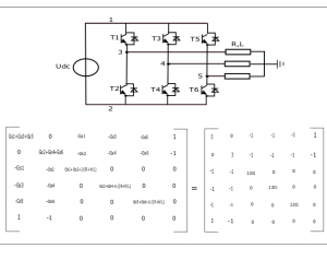
The sparse fixed admittance matrix is solved only once during the whole simulation run. During the subsequent simulation steps, the simulator needs only to multiply the history source current vector with the already solved fixed sparse LU-matrix to calculate the solution vector. The number of additions and multiplications needed for the solution vector is very small compared to the full LU-matrix solution (less than 0.3%).

Unlike the Pejovic -associated discrete circuit-technique, where a very small time step (much less than 1 micro-second) is required to get an acceptable accuracy, the new proposed fixed admittance matrix technique can work with much larger time step (some tens of micro seconds) for the same simulation accuracy.

Electrical machines can be simulated by both Simulators; the non fixed admittance simultor SimuPec® as well as the fixed admittance simultor SimuPecFA®, not only as interfacing models but also as embedded models to the whole power electronics system.

The electrical and mechanical equations of the electrical machines by the fixed admittance matrix simulation are decoupled using the values from the previous fixed Point iteration within the same time step.

The unique features of the new proposed fixed admittance matrix technique make it very suitable for large scale off-line, real time and hardware in the loop Simulation.   

SimuPec Features:

The following is a partial list of useful features to give the user an indication of the versatility of SimuPec:

  • Two power electronics simulators; SimuPec® which is a conventional non fixed admittance simulator and SimuPec_FA® the Fixed admittance matrix simulator.
  • Circuit Partitioning and decoupling (for both Simulators SimuPec_FA and SimuPec)
  • Interactive and Dynamic Parameters Variation (non-fixed admittance Simulator SimuPec only)
  • Modeling of Nonlinear and Time Variant Components
  • Modular multilevel converter blockset “MMC-BLOCKSET

SimuPec® and SimuPec_FA®:

SimuPec® is a conventional non fixed admittance simulator and SimuPec_FA® the Fixed admittance matrix simulator. Both of them  can simulate the same power elecronics system without any modifications of the C-Circuit describtion file.

Circuit Partitioning and decoupling:

SimuPec® and SimuPecFA® make use of system-partitioning by dividing the whole large scaled power electronics system containing thousands of switching device, thermal and electromechanical devices into many small sub-systems with different scale of time constants. This leads to remarkable speedup over single system (single very large system matrix).

A single time step delay is needed only if the S-function block needs to communicate with other blocks, for example in the MMC-converter there is no need of any time delay between the S-function blocks of the converter arms because there are no communications needed between each others. Between the S-function block of the converter arms and the main power supply circuit you should add single time step delay.

The figure below shows one MMC-converter station modeled as 7 Simulink blocks. One Simulink block for each arm (half leg) of the converter and one Simulink block for the power supply circuit.

The circuit topoloy of the 6-arms of converter are exsactly the same, they make use the same paramter-vector, however they need different input-vector and deliver different output-vector. Therefor you need to model only one converter arm and use it (copy and paste) for the other converter arms after modification of the respective input-vector and output-vector.      


MMC Conveter station modeled as 7 S-function blocks

The basic model of the switching devices by the fixed admittance Simulator is a fixed admittance G=1/ohm during both switching states; although different values are used in the history source current Vector.

By the non fixed admittance Simulator, the basic model of the switching device is a piecewise linear model. The resistance value changes according to the switching state, it takes a very high value (Roff>1e6) in the turn-off state and a very small value (Ron<1e-3) in the turn-on state. The transition between these two states takes place instantaneously.

Interactive and Dynamic Parameters Variation (SimuPec only):

All components parameters can be defined not only as constant values or as elements of the Simulink parameter vector p[0, 1, 2, …] but also as elements of the Simulink input vector u[0, 1, 2, …].  Components parameters can be interactively changed during the simulation by changing the value of the Simulink parameter vector in the Simulink model. They can also be dynamically defined by any Simulink’s block via the input vector u[0, 1, 2, …].

The number of basic components offered by SimuPec is very small compared to other simulators. There is only e.g. one general purpose Resistor . The same is true for the general purpose inductors, capacitors, voltage and current sources etc. The reason for this is the possibility of dynamic variation of the components parameters.

Modeling of Nonlinear and Time Variant Components:

SimuPec provide two methods to model nonlinear and time variant circuit components (R, L and C).

  1. You can use the built-in nonlinear circuit components (R_NL, L_NL and C_NL).
    • The nonlinear resistance R_NL is modeled as a current source its value is a function of the voltage on R_NL, either as an equation i=f(v)  or in tabular form.
    • The nonlinear inductance L_NL is modeled also as a current source its value is a function of the flux linkage ψ of L_NL, either as an equation i=f(ψ)  or in tabular form. The flux linkage on L_NL is caculated in simulink by integrating the voltage drop on L_NL.
    • The nonlinear capacitance C_NL is modeled as a voltage source its value is a function of electrical charge on C_NL, either as an equation v=f(Q)  or in tabular form. The electrical charge on C_NL is caculated in simulink by integrating the current through C_NL.
  2. You can use the built-in circuit components (R, L and C) and deliver the instantaneous value of the circuit components (R, L and C), depending on the current or voltage of these components, either as equations R=f(v),  L=f(i) and C=f(v) or in tabular form.

MMC-Blockset

The new MMC-Blockset contains Simulink-blocks to model and simulate any number of levels of the modular multilevel converter in Matlab/Simulink environment without a need for any power electronics toolbox.

The MMC-Blockset contains simulink models based on the Simulink C S-functions for many of the well known MMC-Topologies, the half bridge (HB-MMC), full bridge (FB-MMC) and the clamped double submodule (CDSM-MMC) as well as many power supply circuits with different transformer connections.

Some of the features of this new developed Blockset can be suumarized as follows:

  • All the developed Simulink-blocks use detailed switching devices IGBTs and Diode ;
  • All the developed Simulink-blocks use only Simulink C-S-Functions;
  • All the developed Simulink-blocks behaves exactly like builtin simulink blocks, they have their own parameters, they can be copied and pasted;
  • The simulation is very fast, because each Simulink-block has a small system matrix. The system matrix of, for example the MMC_HB_1L_ARM has matrix dimensions of only 2*2, the system matrix of MMC_HB_200L_ARM has matrix dimensions of only 400*400.
  • Users are allowed and encouraged to extend and modify the Blockset by adding MMC-ARMs containg other MMC-Topologies, such as three level submodules.
  • There is no need of any power electronics toolbox.

The half bridge HB_MMC_ARM Blockset contains the following HB_MMC_ARM-Levels:

  • MMC_HB_1L_ARM
  • MMC_HB_2L_ARM
  • MMC_HB_5L_ARM
  • MMC_HB_10L_ARM
  • MMC_HB_20L_ARM
  • MMC_HB_50L_ARM
  • MMC_HB_100L_ARM
  • MMC_HB_200L_ARM

The full bridge FB_MMC_ARM Blockset contains the following FB_MMC_Levels:

  • MMC_FB_1L_ARM
  • MMC_FB_2L_ARM
  • MMC_FB_5L_ARM
  • MMC_FB_10L_ARM
  • MMC_FB_20L_ARM
  • MMC_FB_50L_ARM
  • MMC_FB_100L_ARM

The clamped double submodule CDSM_MMC_ARM Blockset contains the following CDSM_MMC_Levels:

  • MMC_CDSM_2L_ARM
  • MMC_CDSM_10L_ARM
  • MMC_CDSM_20L_ARM
  • MMC_CDSM_50L_ARM
  • MMC_CDSM_100L_ARM
  • MMC_CDSM_200L_ARM

The power supply circuits blockset contains the following power supply circuits:

  • MMC_MC_TYD
  • MMC_MC_TDY
  • MMC_MC_TYY
  • DC-CABLE
  • CAUER-THERMAL-CIRCUIT

The MMC-CONTROL blockset contains the following components:

  • Triangular Generator for MMC
  • General Purpose Triangular Generator

How to use the MMC-Blockset:

The Figure below shows the model of a MMC_HB_71L-Converter using one 50L- Submodules and one 20L-Submodules. The arm voltages of the MMC_HB_50L_ARM and that of the MMC_HB_20L_ARM are added to get the total converter arm voltage. The 50 capacitor voltages of the MMC_HB_50L_ARM and the 20 capacitor voltages of the MMC_HB_20L_ARM are multiplexed to get the 70 capacitor voltages. The Memory block is required to break the allgebriac loop.

The Components parameters can be interactively changed during the simulation by changing the C S-functions  parameter-vectors.

The parameters mask of the MMC_HB_50L_ARM is show below.

The parameters mask of the main circuit containing the power supply, the main circuit breaker and the power transformer MMC_MC_TYD is show below.


Simupec Version

SimuPec license is locked to your spesific MATLAB license number (you can get the Matlab license number by typing “license” in the MATLAB command line).

All informations which submitted by pressing “Send” will be kept confidential and handled conform to the data protection act!!!

Error: Contact form not found.

Trial Version

Order a FREE TRIAL version of SimuPec/SimuPecFA for Microsoft windows. With this version You can model and simulate power electronics System including electromagnetic components in conventional variable Admittance using SimuPec and in the new fixed admittance Matrix using SimuPecFA with unlimited Matrix dimensions for a time period of one month. 

The real time Code Generator and the MMC-BLOCKSET are not included in the free trial Version. 

SimuPec license is locked to your spesific MATLAB license number (you can get the Matlab license number by typing “license” in the MATLAB command line).

All informations which submitted by pressing “Send” will be kept confidential and handled conform to the data protection act!!!

Error: Contact form not found.

About Us

SimuPec-XXL
Prof. Dr. –Ing. Samir Salama
samir.salama@simupec-xxl.eu

samir.salama47@yahoo.de

Power electronics and drive system consulting:

We offer a variety of consulting, simulation and design services, including, but not limited to:

    • Power converters:

AC-DC-Converters
DC-AC-Inverters

DC-DC-Converters

Switch Mode Power Supplys

Resonant and soft-switching Converters

Multlevel neutral point clamped Convereters

Multlevel floating capacitors Convereter
Static VAR Compensators.

    • Power electronics for renewable energy sources:

Power electronics for Photovoltaic systems
Power electronics for wind power systems

    • Drive system design and control:

DC motor drives
Induction motor drives
Synchronous motor drives
Permanent magnet Brushless dc (BLDC) motor drives
Vector controlled drives
Direct torque controlled drives.

  • Computer Simulation of power electronics and motor drives:

we have more than 30 years experience in developing and simulation of power electronics and drive systems.

The first patent in 1986: multilevel converter. Patenschift DE 3743437.

Last patent in 2016: active and diode clamped multilevel converter.

We can help you to create  a model of your system in the Matlab/Simulink® environment.