
Dengue und Malaria⁚ Zwei Tropenkrankheiten mit Gemeinsamkeiten und Unterschieden
Dengue und Malaria sind zwei weit verbreitete Tropenkrankheiten, die durch Mücken übertragen werden. Beide Krankheiten können schwerwiegende Folgen haben, aber sie unterscheiden sich in ihren Ursachen, Symptomen und Behandlungen. Dieser Artikel soll einen Überblick über diese Krankheiten geben, ihre Gemeinsamkeiten und Unterschiede hervorheben und wichtige Informationen zur Prävention bieten.
Einleitung
Dengue und Malaria sind zwei weit verbreitete Tropenkrankheiten, die durch Mücken übertragen werden. Beide Krankheiten können schwerwiegende Folgen haben, aber sie unterscheiden sich in ihren Ursachen, Symptomen und Behandlungen. Dieser Artikel soll einen Überblick über diese Krankheiten geben, ihre Gemeinsamkeiten und Unterschiede hervorheben und wichtige Informationen zur Prävention bieten.
Dengue
Definition und Ursachen
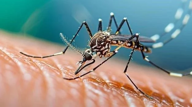
Dengue ist eine virale Erkrankung, die durch das Dengue-Virus verursacht wird, das von der Aedes aegypti-Mücke übertragen wird. Es gibt vier verschiedene Dengue-Virus-Serotypen (DENV-1, DENV-2, DENV-3 und DENV-4), die alle zu Dengue-Fieber führen können.
Definition und Ursachen
Dengue ist eine virale Erkrankung, die durch das Dengue-Virus verursacht wird, das von der Aedes aegypti-Mücke übertragen wird. Es gibt vier verschiedene Dengue-Virus-Serotypen (DENV-1, DENV-2, DENV-3 und DENV-4), die alle zu Dengue-Fieber führen können. Die Aedes aegypti-Mücke ist in tropischen und subtropischen Regionen weltweit verbreitet und bevorzugt städtische Gebiete mit stehenden Wasseransammlungen, wie zum Beispiel in Behältern, Reifen und Zisternen.
Symptome
Die Symptome von Dengue-Fieber treten typischerweise 4-10 Tage nach dem Mückenstich auf. Die häufigsten Symptome sind⁚
- Hohes Fieber
- Schwere Kopfschmerzen
- Muskelschmerzen
- Gelenkschmerzen
- Übelkeit und Erbrechen
- Hautausschlag
- Müdigkeit
In schweren Fällen kann Dengue-Fieber zu lebensbedrohlichen Komplikationen wie Dengue-Schocksyndrom führen, das durch einen starken Blutdruckabfall und Organversagen gekennzeichnet ist.
Diagnose und Behandlung
Die Diagnose von Dengue-Fieber erfolgt in der Regel anhand der Symptome und der Krankengeschichte des Patienten; Laboruntersuchungen, wie z. B. ein Bluttest, können helfen, die Diagnose zu bestätigen und den Schweregrad der Erkrankung zu bestimmen. Es gibt derzeit keine spezifische Behandlung für Dengue-Fieber. Die Behandlung konzentriert sich auf die Linderung der Symptome, die Vorbeugung von Komplikationen und die Unterstützung des Körpers bei der Genesung.
Die Behandlung umfasst in der Regel⁚
- Ruhe
- Viel Flüssigkeit
- Fiebersenkende Medikamente
- Schmerzmittel
In schweren Fällen kann eine intravenöse Flüssigkeitstherapie und eine Überwachung in einem Krankenhaus erforderlich sein.
Prävention
Die effektivste Methode zur Vorbeugung von Dengue-Fieber ist die Vermeidung von Mückenbissen. Dazu gehören folgende Maßnahmen⁚
- Tragen von langärmeligen Hemden und langen Hosen
- Verwendung von Mückenabwehrmitteln
- Vermeidung von Aufenthalten in Gebieten mit hoher Mückenpopulation
- Einsatz von Mückennetzen
- Entfernung von stehenden Gewässern in der Umgebung, die als Brutstätten für Mücken dienen
Es gibt derzeit keinen Impfstoff gegen Dengue-Fieber, aber es werden verschiedene Impfstoffkandidaten entwickelt.
Malaria
Definition und Ursachen
Malaria ist eine durch Parasiten verursachte Krankheit, die durch den Stich infizierter Anopheles-Mücken übertragen wird. Die Parasiten, Plasmodium genannt, vermehren sich in den roten Blutkörperchen des Menschen und verursachen die Krankheitssymptome. Es gibt verschiedene Arten von Plasmodium, die Malaria verursachen können, darunter Plasmodium falciparum, Plasmodium vivax, Plasmodium ovale und Plasmodium malariae. P. falciparum ist die gefährlichste Art und kann zu schweren Komplikationen und sogar zum Tod führen.
Definition und Ursachen
Dengue ist eine virale Erkrankung, die durch das Dengue-Virus verursacht wird, das von der Aedes aegypti-Mücke übertragen wird. Es gibt vier verschiedene Serotypen des Dengue-Virus (DEN-1, DEN-2, DEN-3 und DEN-4), die alle schwere Krankheiten verursachen können. Die Krankheit ist in tropischen und subtropischen Regionen weltweit verbreitet. Die Übertragung erfolgt durch den Stich einer infizierten Mücke, die das Virus von einer zuvor infizierten Person aufnimmt und es dann auf einen anderen Menschen überträgt.
Symptome
Die Symptome von Dengue können von mild bis schwerwiegend reichen. In vielen Fällen verlaufen die Symptome mild und ähneln einer Grippe. Zu den häufigsten Symptomen gehören hohes Fieber, starke Kopfschmerzen, Muskelschmerzen, Gelenkschmerzen, Übelkeit, Erbrechen und Hautausschlag. In schweren Fällen kann Dengue zu lebensbedrohlichen Komplikationen wie Dengue-Schocksyndrom (DSS) führen, das durch einen starken Blutdruckabfall und Flüssigkeitsansammlungen im Körper gekennzeichnet ist.
Diagnose und Behandlung
Die Diagnose von Dengue erfolgt in der Regel anhand der klinischen Symptome und der Anamnese des Patienten. Blutuntersuchungen können helfen, die Infektion zu bestätigen und den Schweregrad der Erkrankung zu beurteilen. Die Behandlung von Dengue konzentriert sich auf die Linderung der Symptome und die Vorbeugung von Komplikationen. Es gibt kein spezifisches Medikament gegen Dengue, aber eine ausreichende Flüssigkeitszufuhr ist entscheidend. In schweren Fällen kann eine intravenöse Flüssigkeitstherapie und eine unterstützende Behandlung in einem Krankenhaus erforderlich sein.
Prävention
Die effektivste Methode zur Vorbeugung von Dengue ist die Vermeidung von Mückenbissen. Dazu gehören Maßnahmen wie das Tragen von langärmeligen Kleidung und Hosen, das Verwenden von Mückenabwehrmitteln, das Anbringen von Moskitonetzen über Betten und das Vermeiden von Aufenthalten in Gebieten mit hoher Mückenpopulation während der Dämmerung und in der Nacht. Die Bekämpfung von Mückenbrutstätten durch Entleeren von stehenden Wasserbehältern und die Verwendung von Insektiziden spielen ebenfalls eine wichtige Rolle bei der Prävention.
Gemeinsamkeiten und Unterschiede
Dengue und Malaria teilen einige Gemeinsamkeiten, wie z.B. die Übertragung durch Mücken und die Symptome wie Fieber. Allerdings unterscheiden sie sich in wichtigen Aspekten. Während Dengue durch das Dengue-Virus verursacht wird, das von Aedes aegypti-Mücken übertragen wird, wird Malaria durch Parasiten der Gattung Plasmodium verursacht, die von Anopheles-Mücken übertragen werden. Dengue-Symptome können von mild bis schwer reichen, während Malaria in einigen Fällen lebensbedrohlich sein kann. Die Behandlungen für beide Krankheiten unterscheiden sich ebenfalls, wobei Dengue-Patienten meist symptomatische Behandlungen erhalten, während Malaria-Patienten spezifische antimalarielle Medikamente benötigen.
Schlussfolgerung
Dengue und Malaria sind zwei ernstzunehmende Tropenkrankheiten, die erhebliche Auswirkungen auf die öffentliche Gesundheit haben. Das Verständnis der Unterschiede und Gemeinsamkeiten dieser Krankheiten ist entscheidend für die Entwicklung effektiver Präventions- und Behandlungsstrategien. Durch die Sensibilisierung der Bevölkerung für die Risiken und die Förderung von Maßnahmen zur Mückenkontrolle können wir zur Eindämmung dieser Krankheiten beitragen und das Wohlergehen der Menschen in den betroffenen Regionen verbessern.
Glossar
- Dengue
- Eine virale Krankheit, die durch den Stich der Aedes aegypti-Mücke übertragen wird.
- Malaria
- Eine durch Parasiten verursachte Krankheit, die durch den Stich der Anopheles-Mücke übertragen wird.
- Aedes aegypti
- Eine Mückenart, die Dengue überträgt.
- Anopheles-Mücke
- Eine Mückenart, die Malaria überträgt.
- Vektor-übertragene Krankheiten
- Krankheiten, die durch Lebewesen wie Insekten übertragen werden.
Der Artikel bietet eine gute Einführung in die Thematik von Dengue und Malaria. Die Beschreibung der Symptome und der Übertragungswege ist klar und verständlich. Die Einbeziehung von Präventionsmaßnahmen ist sehr wichtig und wird in diesem Artikel gut umgesetzt. Der Artikel könnte jedoch durch die Einbeziehung von Informationen zur Behandlung der Krankheiten noch umfassender gestaltet werden.
Dieser Artikel bietet eine prägnante und informative Übersicht über Dengue und Malaria. Die Darstellung der Gemeinsamkeiten und Unterschiede zwischen den beiden Krankheiten ist klar und verständlich. Besonders hervorzuheben ist die detaillierte Beschreibung der Symptome und der Präventionsmaßnahmen. Der Artikel ist gut strukturiert und leicht lesbar. Allerdings könnte die Einleitung etwas ansprechender gestaltet werden, um den Leser stärker in das Thema einzuführen.
Der Artikel bietet eine umfassende und gut strukturierte Übersicht über Dengue und Malaria. Die Darstellung der Gemeinsamkeiten und Unterschiede zwischen den beiden Krankheiten ist klar und verständlich. Besonders hervorzuheben ist die detaillierte Beschreibung der Symptome und der Präventionsmaßnahmen. Der Artikel ist gut lesbar und bietet wichtige Informationen für Reisende in betroffene Gebiete.
Der Artikel ist gut recherchiert und bietet einen umfassenden Überblick über Dengue und Malaria. Die Darstellung der Unterschiede zwischen den beiden Krankheiten ist besonders hilfreich. Die Informationen zur Prävention sind klar und verständlich formuliert. Ein kleiner Kritikpunkt ist die fehlende Einbeziehung von aktuellen Forschungsergebnissen zur Behandlung von Dengue und Malaria.
Der Artikel ist gut geschrieben und bietet eine informative Übersicht über Dengue und Malaria. Die Darstellung der Unterschiede zwischen den beiden Krankheiten ist klar und verständlich. Die Einbeziehung von Präventionsmaßnahmen ist besonders wichtig und wird in diesem Artikel gut umgesetzt. Der Artikel könnte jedoch durch die Einbeziehung von Statistiken oder Zahlen zur Verbreitung der Krankheiten noch informativer gestaltet werden.
Der Artikel bietet eine informative und gut strukturierte Übersicht über Dengue und Malaria. Die Darstellung der Ursachen, Symptome und Behandlungen ist klar und verständlich. Besonders gut gefallen hat mir die Einbeziehung von Präventionsmaßnahmen, die für Reisende in betroffene Gebiete von großer Bedeutung sind. Der Artikel ist jedoch etwas trocken und könnte durch mehr Beispiele oder Fallstudien lebendiger gestaltet werden.
Der Artikel vermittelt ein gutes Grundverständnis von Dengue und Malaria. Die Beschreibung der Symptome und der Übertragungswege ist klar und prägnant. Die Einbeziehung von Präventionsmaßnahmen ist sehr wichtig und wird in diesem Artikel gut umgesetzt. Der Artikel könnte jedoch durch die Einbeziehung von Grafiken oder Bildern ansprechender gestaltet werden.